As we all know, Huawei has been continuously pursuing independent innovation and has achieved one technological achievement after another. After the release of the new Huawei P40 series, a lot of discussions have been triggered. According to the disassembly, the components of Huawei P40 are mainly purchased from China, Taiwan, South Korea, Japan and other places, but American manufacturers such as Qualcomm, Qorvo and Skyworks still provide the necessary Radio frequency (RF) components, and Micron’s NAND Flash seems to have been replaced by Samsung’s NAND Flash.
The Kirin 990 5G SoC chip in the Huawei P40 series is currently one of the 5G SoCs with the most complete frequency band coverage. It is also equipped with the self-developed Wi-Fi 6+ smartphone chip Kirin W650, which is the first model to support Huawei Wi-Fi 6+ The series supports 160MHz bandwidth and the peak rate is up to 2.4Gbps, which is twice the industry level in the same period.

Wi-Fi方面用上了海思自己的Hi1105,支持Wi-Fi 6
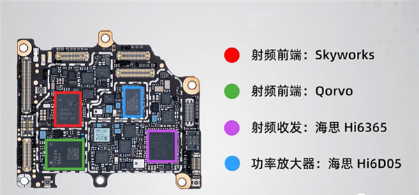
The RF front end comes from Qorvo and Skyworks, but the transceiver and amplifier come from HiSilicon.
The RF front-end module is a key component of a mobile phone, and it is a necessary part for making calls and connecting to the network. The RF front end is a component directly connected to the antenna, which directly affects the wireless signal reception, signal amplification and filtering functions of the mobile phone.
Devices such as mobile phones require terminals to support six CA technologies at the same time. However, existing mobile phones cannot support six or more CA technologies that may be combined at the same time, and their design is not flexible enough.
Analyze Huawei’s RF Channel Technology
To solve this problem, Huawei applied for an invention patent called “Radio Frequency Channel” on February 27, 2014 (application number: 201410069708.2), and the applicant was Huawei Technologies Co., Ltd.
According to the currently open patent information, let us take a look at this radio frequency technology.
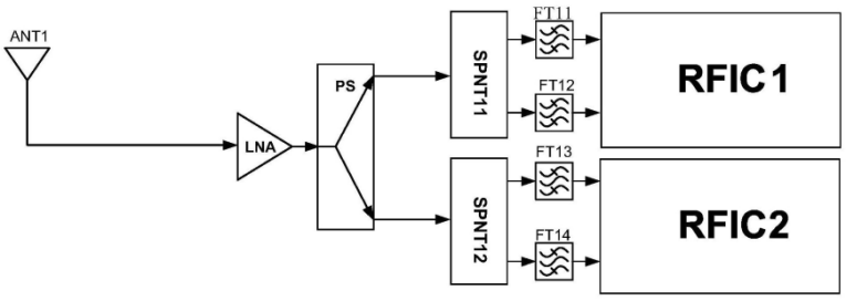
The above figure is a schematic diagram of the structure of the radio frequency path, which can be the main receiver path or the diversity receiver path. The main function of the main receiver is to demodulate the radio frequency signal received by the main antenna into an analog baseband signal, and the main function of the diversity receiver is the diversity antenna. The received radio frequency signal is demodulated into an analog baseband signal.
The radio frequency path includes a first antenna (ANT1), a low noise amplifier (LNA), a power divider (PS), two first single-pole multi-throw switches (SPNT11 and SPNT12), four first filters (FT11, FT12, FT13 and FT14) and two first wireless radio frequency chips (RFIC1 and RFIC2).
So what are the functions of these devices? The antenna receives the radio frequency signal from the wireless channel when receiving, and radiates the radio frequency signal into the wireless channel when transmitting; the low noise amplifier can amplify the power of the received radio frequency signal, reduce the noise figure of the radio frequency path, and improve the receiving sensitivity index; the power divider will The power of the radio frequency signal is averagely divided into two channels; the power amplifier can amplify the radio frequency signal power; the radio frequency integrated circuit can change the radio frequency signal into an analog baseband signal or the analog baseband signal into a radio frequency signal according to the configuration of the internal register of the RFIC.
Each of the four filters corresponds to a filter frequency band. After the antenna receives the RF signal, it transmits the RF signal to the low noise amplifier. The low noise amplifier can amplify this RF signal, and the amplified RF signal will be transmitted to the power amplifier. Divider, the power divider divides the radio frequency signal into two and transmits the two signals to two single-pole multi-throw switches respectively.
The single-pole multi-throw switch is equivalent to controlling the on and off of the radio frequency signal. If it passes, the radio frequency signal is passed to the filter. The filter will filter the received radio frequency signal, and finally the signal will be processed in this way. In the radio frequency chip, the chip demodulates the signal.
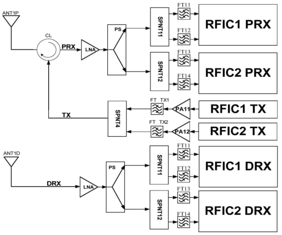
In addition to the RF path, there is also a receiving path. These two paths form the RF front-end. The RF front-end is a device close to the antenna. The schematic diagram of the RF front-end is shown in the figure above. The purpose is to ensure that the useful RF signal can be complete. It is picked up from the space without distortion and sent to the subsequent frequency conversion and intermediate frequency amplification circuits.
As shown in the figure above, the RF front-end includes the main receiver channel PRX, the diversity receiver channel DRX, and the transmit channel TX. Among them, the main set receiving path PRX and the transmitting path TX are connected through a circulator CL, and the structure of the diversity receiving path DRX is similar to the structure of the radio frequency path described above.
The above is the RF channel invented by Huawei. In addition to meeting the six CA technologies, this RF channel also supports the CA RF signal technology between FDD+TDD frequency bands. The received RF signal is divided into two channels through the power splitter. The signal is transmitted to the four filters, so that the radio frequency path can support a variety of combined CA technologies, which improves the flexibility of the radio frequency path. 【Guard reviews】
Future development trend of 5G terminal RF antennas
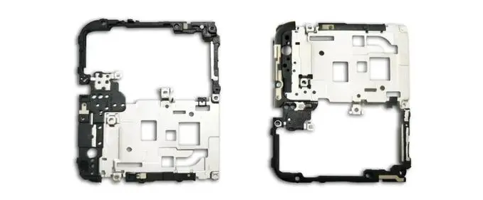
The P40 series are equipped with a “four-curved overflow screen”, which has been treated with arcs around the screen. At the same time, the frame of the phone is further narrowed. These treatments make the positive visual effect better. This design greatly increases the difficulty of antenna design. According to the Guosheng Electronics team’s “A Picture to Understand the List of P40 Core Companies”, the P40 series terminal RF antenna solutions come from Speed and Xinwei respectively. The LDS material used in the antenna bracket comes from Zhongsu, a professional engineering plastic manufacturer. In recent years, with the rise of 5G communications, the innovation of terminal radio frequency antennas and their materials has also advanced by leaps and bounds. Its development trends and salient features are as follows:
1. The function of micro antenna and stable signal is increasing day by day
With the continuous development of mobile communication from 2G, 3G, 4G to 5G, mobile communication antennas have also experienced the development process from single-polarized antennas, dual-polarized antennas to smart antennas, MIMO antennas and even large-scale array antennas. Increasing, and the size is getting smaller and smaller, and to control the commonly used communication frequency band within 4 cm.
The P40 antenna bracket has been enhanced from the original 4G network to the 5G era, the number of antennas has increased and the antenna design position is smaller, and the material requirements are more stringent. Therefore, the P40 antenna uses PC as the base material of LDS functional material. This material may be The stability of the P40 antenna provides a strong guarantee and enables 5G to be controlled in terms of high frequency band and gain.
2. High liquidity is required
Lightweight and thin form and compact structure are the trends of future mobile phone design. Compared with most 5G mobile phones, the P40 series mobile phones are lighter and thinner, and the built-in antenna signal parameters are more stable, which increases the difficulty of antenna structure design.
At the same time, the P40 series adopts the Insertmolding process, which increases the difficulty of injection molding for the structure. Therefore, the P40 series antenna part needs to use materials with high fluidity and strong bonding force. It not only solves the local 0.2mm structural requirements, but also can be combined with shrapnel of different materials.
3. Anti-stress cracking
The trend toward thinner and lighter mobile phones has led to higher and higher requirements for materials used in mobile phone bracket antennas. The P40 structure adopts the Insertmolding process and forms a thin-walled structure. While PC is selected as the base material, the cracking problem inevitably brings trouble to the structure.
To sum up, with the real arrival of the 5G era, the appearance of lighter and thinner, more complex structure, and non-metallic materials will increase the difficulty of mobile phone RF antenna design. In this case, the choice is more functional and quality. Excellent materials may become one of the key points for 5G terminals. 5G terminal RF antenna solutions based on LDS materials will become mainstream.
Sorted out from: Microgrid, China Plastics New Materials, etc.