OPTENNI antenna matching design and automatic optimization software
OPTENNI antenna matching design and automatic optimization software
Significantly simplify the complex matching simulation process, quickly determine the array antenna excitation amplitude and phase parameters, and improve project development efficiency.
ABOUT software
Optenni Lab is developed by the team led by Dr Jussi Rahola, the former chief antenna expert of Nokia Research Center in Finland, a professional antenna and system matching design and automatic optimization software. Optenni is used for the matching optimization design of ultra-wideband antennas, multi-band antennas, multi-port antennas, carrier aggregation tuning, MIMO, and array antennas. It can greatly simplify the complex matching simulation process, quickly determine the array antenna excitation amplitude and phase parameters, and improve project development effectiveness.
Optenni aims at total efficiency. It can perform LC matching, microstrip line matching, array excitation vector optimization, and can evaluate the potential bandwidth of the antenna and antenna isolation.
Features and advantages
- The software dedicated to antenna matching network design and automatic optimization can quickly complete the matching network design of complex systems, increase the work efficiency by dozens of times, and reduce the requirements for the ability and experience of engineers
- Take the total efficiency of the antenna as the simulation optimization goal, and comprehensively consider various loss factors
- Effectively reduce costs and complete the design with the least number of components
- Linked with mainstream CST, HFSS and other EM software, the antenna data obtained by EM simulation can be easily imported into the antenna matching design and automatic optimization software, and the integrated matching circuit of the software can also be imported back to the EM simulation software for joint verification
- Directly connect to vector net to improve antenna matching performance in multiple environments
- The software supports server and stand-alone installation to meet enterprise multi-environment scenarios
- Built-in a large number of real component model libraries, including inductors, capacitors, switches, tuning capacitors, etc. Ensure the authenticity of simulation results
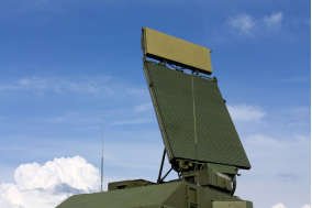
Application field
- Wireless devices, smart phones, wireless charging, wireless routing WiFi, Bluetooth, tablets, cameras
- Millimeter wave IC integrated array antenna, 5G carrier aggregation
- Waveguide array antenna, MIMO array antenna
- Vehicle antenna, access key, tire pressure monitoring, etc.
- Medical hearing aids, MRI scanners, portable patient monitors
The main function
LC matching automatic optimization
1. After importing the antenna EM data or actual measurement results, set the frequency range, which can be single-band optimization or multi-band optimization at the same time.
2. Optimize according to the overall efficiency of the antenna.
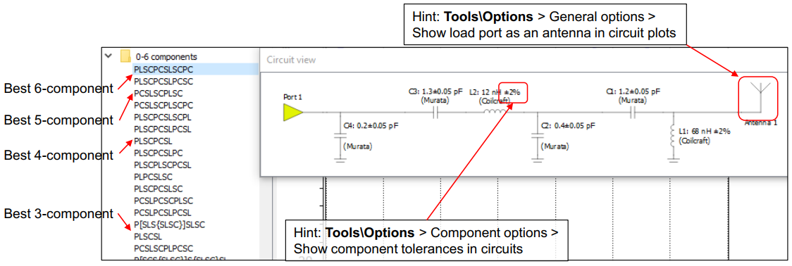
3. Set the order of matching LC. LC can be an ideal device or an actual model from the supplier.
4. The simulation automatically generates the LC matching network, and the result produces a variety of matching topologies for selection.
5. Generate graphs of s-parameters and efficiency parameters.
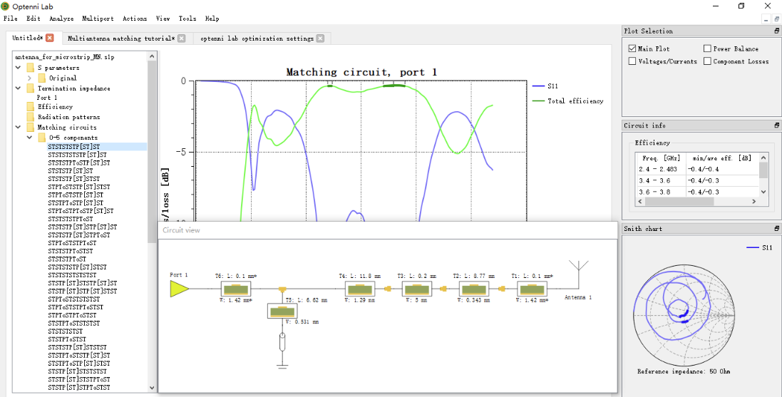
Microstrip line matching automatic optimization
1. In high frequency applications, the microstrip line matching setting window is provided to set the working frequency and the order of the microstrip line.
2. The maximum and minimum limits of the physical size of the microstrip line can be set to ensure that the simulation results meet the actual layout requirements.
3. Provide metal and dielectric material property setting windows to ensure the accuracy of microstrip line simulation.
4. Generate a variety of series-parallel structured microstrip line matching networks, arranged from top to bottom according to performance.
Potential bandwidth assessment
1. Import the antenna SnP file data and observe the unmatched antenna working bandwidth.
2. The software performs preliminary matching of each frequency point of the antenna SnP data and explores some potential available working bandwidth.
3. Evaluate multiple sets of potential bandwidth curves based on indicators such as S11, and then compare and select them.
4. Perform in-depth optimization and matching based on bandwidth evaluation results.
Loss factor assessment
1. Import antenna SnP file data and radiation pattern data, and the software can analyze multiple loss factors.
2. When the antenna is optimized, the total efficiency of the system is the optimization goal, and the simulation results can feed back the proportion of each loss factor.
3. Loss factors include reflection loss, device loss, coupling loss, antenna inherent loss, and the software can generate a loss balance analysis chart.
4. You can choose to observe the proportion of loss factors in different frequency bands.
Robustness evaluation
1. Carry out LC matching device error and system stability analysis, the software can set the error size of LC model of different suppliers.
2. The evaluation times can be set, the more times, the denser the error curve distribution.
3. After the evaluation is completed, the software will reorder the previous matching networks and arrange them from top to bottom according to the stability of the system.
Component power overload evaluation
1. The actual LC model built in the software contains peak voltage or current parameters for component power overload evaluation.
2. Provide an excitation input window, and set the excitation amplitude according to the actual output of the PA.
3. After evaluation, the peak power curve of each LC component in the matching network is given.
4. After the evaluation, the power overload component is highlighted in red.
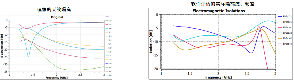
Isolation evaluation and active reflection coefficient optimization
1. Import the SnP file data of multiple antennas or phased array antennas, and initially observe the isolation between antenna elements.
2. The software can perform preliminary background matching of each antenna unit, and quickly evaluate the worst isolation situation.
3. Perform port matching optimization for each antenna unit.
4. Analyze the isolation through the active reflection coefficient, observe the Smith chart for the optimized matching network, and select the matching network corresponding to the best active reflection coefficient.
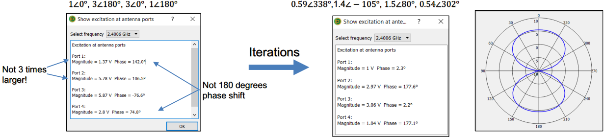
Array excitation vector optimization
1. The software can quickly evaluate the result that the excitation vector of the array unit is affected by the isolation.
2. The software can quickly evaluate that the excitation vector is affected by the difference of the array unit matching network.
3. For simple arrays, you can manually set the window to fine-tune the excitation vector to meet the final beamforming target value.
4. For large-scale phased array antennas, it can automatically optimize the array element excitation vector according to the expected result of beamforming.
